 home
home
 back
back
Of all the tools available to the audio engineer charged with setting up systems be they studio monitors, back-ground music installations or concert systems for 30,000 people, probably the most useful is the phase checker. It can save may hours chasing odd system behaviour and strange effects that are caused by simple wiring faults or basic incorrect system settings. In the case of faulty wiring, the time saving can be massive if the only cure is to get the riggers out of the pub and send them up the truss the replace one cable with a +/- cross connection.
These things and their names are very often a source of confusion and misinformation in the audio industry. All too often the Φ symbol is used on a piece of equipment to signify a polarity reversal (effectively + becomes – and – becomes +) which has very little to do with true phase issues:
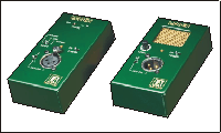
Most phase checkers come as two separate boxes – a pulse generator and a pulse detector. I use this product form LA Audio:

The left hand unit is the detector with an XLR input switchable for line or mic level or there’s an internal mic on the far end of the box. The right hand unit is the pulse generator which has an XLR line output and a small speaker output. Both units are switchable between pin 2 and pin 3 hot on the XLR connectors.
The pulse generator produces a pulse wave which looks something like this:

This is fed into the system under test and the output is fed into the detector which looks at the polarity of the pulse it receives. If it receives the same polarity of pulse then it shows a green led. Like this:

If it sees a pulse that looks more like this it will show a red led:

In practice the pulse gets chewed up by filters as well as loudspeaker responses but the critical bit is the leading edge crossing the detection threshold - positive going shows green, negative shows red.
This is a typical way to connect a phase checker to test a loudspeaker system:

Since the detector is a fairly simple soul and simply detects the polarity of the first pulse above it’s detection threshold so it is important not to confuse it by feeding it pulses from multiple sources at the same time; as far as possible test only one unit at a time - mute or disconnect everything else. This way you can quickly run through the system one box at a time. Ideally you would test your system in this way as you 'flash' through it before flying it. That way cable faults can be corrected more easily.
Typical results are these:

There are many reasons why different components in a loudspeaker system might be deliberately set out of phase: compensation for time alignment between horns and direct radiating drivers, compensation for crossover distortion for example. It is very common for a pulse-phase-checker (such as this) to give a green light on the mid-range and a red light on the HF, as shown above; this is not necessarily wrong. The best solution is to get to know the system you are using and if you don't, compare like for like; if there is one box that gives a different result from all the others there is a problem that needs investigating. For example if all but one of your loudspeaker systems shows the results above and one shows this:

then look at any of the flagged points:

Generally speaking the lower the frequency (and so the longer the wavelength) the more noticeable phase problems will be. This is because the physical positioning of sources and reflective boundaries will be fractions of wavelengths apart and thus cause the most cancellation effects. So as far as possible - and this is especially important when you are mixing non-identical speaker systems - try to get your subs in phase first and then work up through your frequency range. Good manufacturers should maintain a characteristic approach to system design. For example all d&b subs behave the same way with respect to each other and the low-midrange response of their systems so that any sub can be used with any hi-mid cabinet.
As you move up through the frequency range polarity reversals within systems are common to compensate for many real-world problems in loudspeaker cabinet design both in active and passive systems which are far too subtle for a simple pulse-generator/detector system to measure. However higher frequencies contribute much more to your sense if imaging - which is why you should always use identical left and right systems in critical applications. For this reason I would always advocate sourcing as much of you system as possible from the same manufacturer and one with a sensible approach to phase response for those critical applications.
In audioplus number 7, 1993 d&b published the following advice on the use of phase checkers. The full scope of the article discusses the effect of the transfer function on the phase-checker's pulse wave and the potential errors that can arise. This extract is taken from page 3:
Provided the following advice is adhered to, most phase checkers should give consistent results when testing identical loudspeaker systems :
Phase reversals are most commonly found in the wiring of the cables of the signal chain. Apart from checking loudspeaker polarity, and provided active crossovers, equalisers and effects units are excluded, a phase checker will normally provide correct and consistent indication of a polarity reversal in the signal chain.
Thanks to d&b audiotecknik for permission to reproduce this extract.