 home
home
 back
back
In the briefest possible terms, the aim of delaying a system is to make the reinforced sound arrive at the listener at the same time as the natural or the sound from one loudspeaker to arrive at the same time as that from another. The result of this is to improve intelligibility and 'imaging' - that is to make the sound appear to come from the performer rather than the loudspeaker system. Knowing how we perceive the sound we hear can help us achieve a better result more easily.
In the real world, in all but anechoic situations (outdoor systems can approach anechoic conditions) the sound the listener hears is a mixture of direct and reflected sound. The auditory systems of the ears and brain attempt to interpret this mixture into an integrated and coherent pattern of intelligible information. Quite extensive research has been done into how much reflected sound and at what time intervals can be deciphered before a listener starts to hear echoes that confuse and reduce intelligibility.
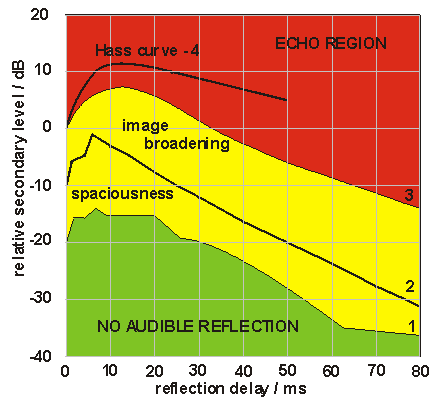 fig. 1
Helmut Hass working in the early 1950's produced the top curve (4) shown in fig.1. In this research he showed that a secondary source (reflection or delay) could be up to 10dB louder than the primary source and yet not be perceived to be as loud for delays within a 10 to 25ms range. This result is often misunderstood as meaning that within this time delay a secondary signal has to be 10dB louder than the primary source before the localisation to the primary source (imaging) is lost. Hass actually stated that at +10dB the secondary source would be perceived to be as loud - so clearly it has been perceived as a source in its own right - and therefore the imaging has been confused - at a much lower level. In practice this level turns out to be more like 4dB
Looking at the other curves in fig.1 this becomes apparent. This shows research by Lochner & Burger (1958) and Olive & Toole (1989) in which listeners were required to identify when and in what way, a delayed signal became apparent, in the lateral plane, as the relative level and time delay were altered when fed into a second loudspeaker to the side of the first. Within the green region there was no audible effect on the listening environment. In the yellow region the listening effect moved through a subtle effect of spaciousness through to a definite broadening of the image.
In live reinforcement applications the echo perception threshold (curve 3) is the most important. When combined with the precedence effect which describes the phenomenon whereby listeners identify the first sound arrival direction as the source direction and then ignore all early reflections within a window of about 30ms. In fact arrivals within this 30ms window are actually combined within the aural processing to reinforce each other into one coherent sound. Thus, for most practical applications, keeping the direct to delayed signal delay and level ration within the yellow region ensures that intelligibility is maintained and imaging is manageable. The closer to the green region the better the imaging and integration will be, the closer to the red region the worse it will be. There is a vast amount of information on this topic for those who want to research it further.
In some cases we are simply concerned with achieving the maximum intelligibility but often in the case of audio systems for performance we are also interested in the perception of an image i.e. the apparent source of the sound, an actor or musician for example. Correct use of delay is essential to both of these goals. By attempting to delay the sound arriving from a loudspeaker to coincide with the arrival of the natural sound (or the sound from the previous loudspeaker in multi speaker systems) we hope to persuade the auditory system of the listener that he is hearing only one sound from the actual source.
Another misinterpretation of the data in fig.1 is that if a loudspeaker and the actual source are less than 30ms apart then you don’t need to delay the loudspeaker. This fails to take into account the reflections that the loudspeaker will generate in addition to those already created by the original source, clouding intelligibility, as mentioned above and the image shift that will occur. In practice even a relatively small amount of delay (5ms or so) can have a massive effect on shifting the perceived image to where you want it to be.
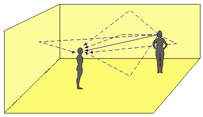 fig.2
fig.2
Consider two people in an ‘average’ room, one speaking and one listening (shown in fig. 2). The direct sound from the person will arrive first (solid blue line) a small number of milliseconds later a reflection will arrive from (in this case) the ceiling (reflections are shown as dotted lines). Next will come a reflection from the floor, then the nearest wall then the next wall and so on. Each reflection will go on to reflect of the next surface and diminish in intensity as it does so. The reflections of reflections start to move us into the field of reverberation which does not concern us here. All of these reflections are integrated by our auditory system into one coherent speech pattern provided that the reflections fit into the green or yellow areas in the diagram above. One important issue is the first arrival, this is the key which the auditory system uses to fix the location of the sound in space. Where you hear the first sound coming from is where you perceive the sound source to be. Very dry and small spaces will have reflections damped and/or with short times which will lie in the green region. More realistic spaces will fit into the upper green or yellow areas giving a feel a spaciousness to the listening environment, although it may be harder to precisely pin point the sound source without visual clues.
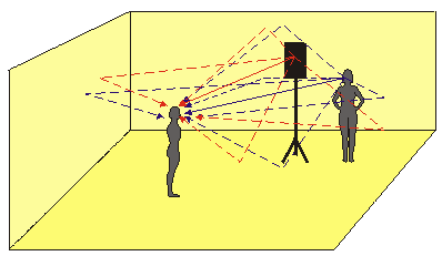 fig.3
fig.3
Once we start to reinforce natural sound with loudspeakers as in fig. 3 we introduce more confusion into this pattern of reflections and delays. If the speaking person is amplified through a loudspeaker then unless the loudspeaker occupies the same point in space as the person’s mouth (somewhat impractical) then there are two sound sources. The greater the distance between the speaker (person) and the loudspeaker the greater the natural time delay due to the finite speed of sound in air. This has two effects:
Firstly a note of caution. Before attempting to do any delay time setting always, always check the relative ‘phasing’ of your loudspeakers. It is especially important that the drivers of your main left/right, front fills, centre cluster or whatever are moving in the same direction. It is less important for a row of delay speakers half way down the auditorium. Incorrect wiring of a multi-core or a ‘phase reverse’ option selected on a crossover that goes unnoticed at this point will waste you a lot of time when you come to the listening test as things just won’t sound ‘right’. Get used to what a stereo system sounds like with one loudspeaker’s phase reversed and if you only carry one piece of test equipment a phase checker is probably the most valuable.
Be aware that some loudspeakers deliberately have the high and mid frequency drivers out of phase – and the transform functions of the crossover and driver frequency response can have an effect on the apparent ‘phasing’ of the loudspeaker. In most cases I tend to use the mid-range driver as the reference when comparing unlike boxes since this carries most of the essential auditory information. When performing a phase check look for the one loudspeaker or cluster that gives a different result to all of the others and think how one simple wiring fault or processor switch option could cause that – it is very rare that there is more than one such simple fault.
See using phase checkers
The speed of sound is given by (t is temperature in °C):

For air at an average room temperature of 20°C the speed of sound works out at about 344ms-1 (metres per second, can also shown be as m/s). This works out at about 34cm for every millisecond. The approximate time delay between any two points can be roughly calculated by measuring the distance and multiplying by three to give milliseconds if you measured in metres or simply reading feet as milliseconds. If you have a calculator to hand, the following formula gives you a more accurate result:
delay time = distance/344 for meters
delay time = distance/1129 for feet
In all these examples I have assumed a performer wearing some form of lavalier, headset or other close microphone so that the microphone receives a direct signal with no significant acoustic delay.
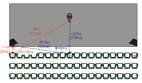 fig.4
fig.4
Consider this example of a small stage shown in fig.4. A performer roughly centre stage is about 3.5m (10ms) from somebody sitting in the centre of the front row (seat 9) and about 6m (17ms) from somebody sitting at the end of the row (seat 1). Assuming that there are loudspeakers either side of the stage then the outer speakers will be about 5.5m (16ms) from seat 9, but only about 1m (3ms) from seat 1.
I have used the symbol δt to symbolise the difference in arrival time. I have avoided the use of positive or negative δt – it is always shown positive. You should pay attention to which source arrives first, for imaging purposes the natural sound should arrive first.
With no delay on the PA system:
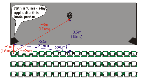 fig.5
fig.5
If we now add a delay of 16ms to the PA1, shown in fig. 5 (slightly more than the extreme delay at seat 1 between the stage and the PA):
1: If you are interested purely in intelligibility then the exact δt will be fine. If you are trying to create in image shift back to the point of origin or as near as possible then I find that adding between 2 and 6ms to the actual value is beneficial.
This is a rather simple but practical approach that takes no account of the relative level of the arrivals which as you can see have a great deal of effect on the perception. But sensitive use of ears is the best way of determining this factor. After all any calculations that you make in this way should always be checked ‘by ear’. There will be some cases where you need so much delay with a layout like this that the effect on the central seats is unacceptable – in which case you might need to compromise the outer seats for the benefit of the majority. This is one situation when ‘flying’ the PA is advantageous since it will lessen the range of distances between sections of the audience.
With quiet performers, loud shows, wide stages or just large performer to audience distances the use of front fills can be of immense help in both imaging and intelligibility. I am a great fan of front fills as they are so much easier to rig than centre cluster systems especially on the time and budget constraints of touring shows.
Again looking at our small theatre and the natural time delays but for the time being we will ignore the main system:
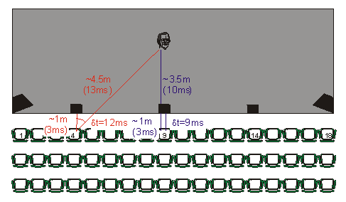 fig.6
fig.6
Applying the same principles as before, paying attention to ensuring that the natural sound arrives first gives us the results in fig.7:
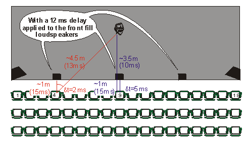 fig.7
fig.7
Here we have added a delay of 12ms to the front fills. Looking closely at the results:
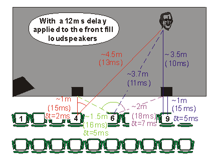 fig.8
fig.8
Fig.8 shows in more detail the rather complex situation that is building up along the seats of the front rows, I have taken seat 6 as an example. We could go further and consider the main system in a similar way; I have left this out of the diagram for the sake of clarity but the results are favourable with the 14ms delay we found before. In all cases the multitude of arrivals will be interpreted by the listener’s auditory system as ‘reflections’ since they are all within the yellow or green regions depending on the level.
You can see here and in the previous diagram that although this simple system of having all the front fill loudspeakers on the same delay works, an improvement could be made by having the central one about 3ms shorter. This would lessen the differences in δt across the row. In practice all your front fill loudspeakers on one delay is cheaper as they could all be fed from one amplifier channel so it is a small budget factor for consideration.
Having got this far if you have time you should consider the possibility of varying some of the times and levels slightly by ear in order to fine-tune the imaging. When doing so, always be prepared to go back to what you had before - you might have got it right first time around.
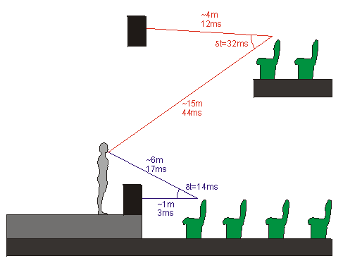 fig.9
fig.9
Another situation is the multi-level auditorium of fig. 9. In this case look at the delay triangles in cross section rather than plan, trying to consider the best compromise at the worst seats. Otherwise the process is identical. Taking the example from before in section view, the seats shown are the end seats in each row, although the performer is standing centre stage as before. The diagram shows a cross section through a left/right system on two levels.
With this simple section view it is hard to indicate the three-dimensional distances involved but I have taken the values from the plan view for the lower seating as an example. So applying the same principles as before with the values for lower seating taken for granted gives us a similar compromise of delay times shown in fig. 10.
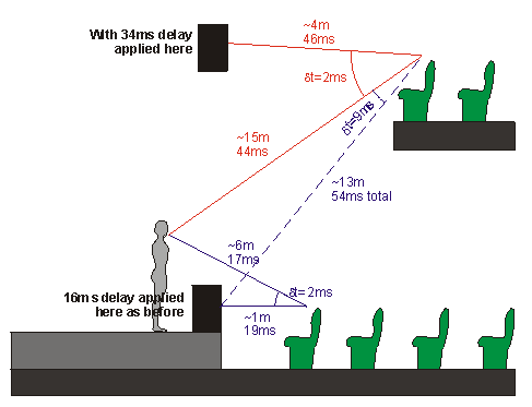 fig.10
With very tall auditoria the stage as the source image becomes less relevant as you move up and away from it. In this case it becomes a matter of timing the sound from each level of loudspeaker to arrive with that of the previous level. This depends on the shape and size of the building and where you can physically position your loudspeakers.
Here the end seat of the upper level hears the natural sound arriving 2ms before that of the nearest loudspeaker, sound from the stage loudspeaker arrives 9ms later so everything fits nicely into the early reflection yellow region of the diagram above, providing that relative levels are correct.
Having the luxury (as it so often is) of being able to fly a central cluster that will cover a large area of your audience from one point source can solve a lot of your problems before they have even occurred. Using a centre cluster as your principle reinforcement system can help imaging and intelligibility by reducing the number of arrivals from loudspeakers since one centre cluster can effectively replace a multi level left/right system. In practice front fills are useful to the imaging of the front rows and some left and right system may be necessary either for stereo effects, separation of the backing music (live or otherwise) or just to fill in any holes not covered by the centre cluster.
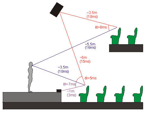 fig.11
Looking at a two level theatre of the same format as before, but fig. 11 takes a cross section along the centre line so we are looking at seat 9. The positioning of the cluster already works for the lower seats with no delay and in a single level theatre that would be acceptable, but we need to look at the upper seats.
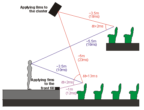 fig.12
In fig.12 we have added delay for the cluster and the front fills. The δt from the cluster and natural sound to the front seats seems a little long at 13ms. In practice this will probably be fine as the level difference from the front fills to the cluster will take this δt further down towards the green zone and our auditory systems are rather poor at differentiating in the vertical plane. Avoid trying to use different delay times for different elements of a cluster to compensate for this, as the comb-filtering effects can be horrendous.
The next consideration is given to the use of specific delay systems to take over when the main system is starting to wane. This could be anything from the smaller loudspeakers often put under balcony overhangs in some theatres or the delay towers at outdoor concerts. In this situation it is sometimes easy and practical to consider the sound from the main system as a plane wavefront. So measuring the distance from the PA to the delay speaker should give you the approximate time delay that you require once you have added the delay applied to the main PA. But consider the situation in fig.13:
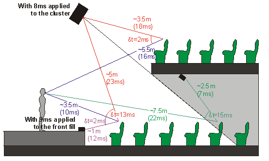 fig.13
The grey area underneath the balcony is masked from the main cluster, so small delay speakers have been rigged to compensate. Starting with the delays already set for our cluster system gives us the times shown. So with no delay set on our under-balcony speakers there is an early arrival of 15ms.
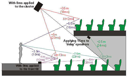 fig.14
Fig 14 shows 17ms of delay added to these so we have a late arrival of 2ms which should move the image back to the stage. But take note of the arrival time we have created from the front fills. This is 2ms later still so if the sound from the front fills is louder at this point than the natural sound or the even later sound from the cluster this might cause the image to shift back up to delay speakers as the first arrival – unlikely but possible. Only your ears will tell you this in such situations and it may be necessary to adjust delay times in other parts of the system to reach the best compromise, although usually increasing the delay time to the under-balcony speakers will solve the problem.
Whether you are approaching the setting of delays by ear or other wise, it is always necessary to define time zero. The simplest way is to use a single loudspeaker fed from an independent output. If you want time zero to be a performer’s mouth, centre stage then put a loudspeaker there – on a stand if necessary.
If you are approaching the process by ear choose some program with short clear transients, for example: a hi-hat loop, a repeating short high frequency bleep or a repeating click all with an interval of about half a second.
For each loudspeaker position it is always a good idea to have worked out roughly the δt even if only by estimating the distances by eye. That way you know the ballpark range that your delay time will fit into. Although certain situations may dictate a slight change from this pattern it is usual to work away from time zero starting with the loudspeakers closest to this point and moving progressively to those with higher expected delay times. The one exception to this is a system with a centre-cluster, for these I would start with the front fills (if you have any) then do the centre cluster next before moving on to any left/right or other components.
Start by listening to your test signal through your reference speaker, and then slowly add the signal to the first loudspeaker to be set (let’s say our front fills). Once you have them at a similar level from your listening position you should hear a distinct image in the front fill speaker, even if it not quite long enough to be considered an echo. Slowly increase the delay time to approach your predicted value. As you do so you should hear the image shift back to the reference loudspeaker. Eventually the front fill should virtually disappear from your aural image. Try varying the level slightly just to see how loud you can go or if you need to reduce the level to avoid noticing the front fill’s presence.
Once you are satisfied with the first delay turn off this loudspeaker and move onto the next one (PA left in our small theatre – I am assuming that we don’t have a central cluster). Perform the same listening test until you are happy with the delay/level combination. Now listen to both PA left and front fills together, try adjusting the relative levels or trimming the delay times if you feel it is necessary but always make a note of your starting point in case you need to go back. Now you should be able to copy the same delay time to PA right and double check the effect on the other side of the auditorium.
Keep on working the same way for all other loudspeakers – comparing each one in turn to only the reference speaker before listening to the overall effect once you are happy.
The are several computer based measurement packages which can help this and other processes to be faster and more accurate. The one I am most familiar with is SMAART, so that's the one I'll talk about.
For more information see www.siasoft.com
Firstly another word of caution, SMAART is a very useful tool in this application but it is just that – a tool. Like most tools it can become dangerous in the wrong hands. I won't attempt a lesson on how to use SMAART here, just how it can be used to help you find your system delay times.
Basically SMAART looks at the difference between two audio signals – whether they are fed directly into the sound card line input or a more sophisticated device isn’t really critical since we are making comparisons. The right input is taken as the reference and the left as the measured signal. The differences can be displayed in a variety of ways. One function measures the time delay between the reference right and measured left. SMAART does not tell you what delay times to put into your system – you still have to deduce that from the information given to you by SMAART. What SMAART can do is make the whole process much faster and more accurate by direct measurement of the δt shown above.
The easiest way to use SMAART for setting delays is to set up a time zero reference speaker as above. Then place your test microphone in some suitably bad seat such as close to a front fill then measure the time delay from the reference speaker and the time delay from the front fill. Subtract the two to give you δt, which your delay time starting point. I say starting point because the vital listening test will probably dictate the addition of a few milliseconds for the sake of better imaging.
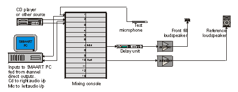 fig.15
Fig.15 shows how I typically set up SMAART for delay timing, there are other ways so this is just one example.
Close miking is very common in theatre shows with head-worn radio microphones which pick-up the sound almost instantly as it leaves the performer’s mouth. But often ‘float’ or ‘gun’ microphones are used to pick up chorus singers which may be a number of metres away from the performers. The problem here is that you actually want to take some delay off the float microphones. Since that isn’t possible you could introduce some delay into the radio microphone send with a possible reduction in the overall system delay to compensate. In practice this is likely to be an expensive luxury, since any gun microphones have to be no further than 2m (6ms) away to be of any practical use in most applications. The small additional delay time this gives will actually help to place the chorus singers ‘behind’ the principles in the final mix. But it may be worth considering the delay of the close microphones to the distance ones in some situations, especially as digital consoles become more common where delay is available on every channel. See also TiMax applications below.
With all performers close miked and fed into the same mix the natural sound from the upstage performers will arrive later than the amplified sound due to the increased distance. One solution to this is to set up two or more mix busses with different delay times and assign performers to these depending on their position on the stage. The problem here is that performers move! Cross fading between fixed delayed busses can create potentially horrific comb-filter effects that are to be avoided.
Possible solutions include setting up multiple ‘delay groups’ and switching performers between them in pauses or breaths as they move about the stage – obviously automated routing systems can make this much easier. Another solution is to use real-time midi controller data to vary delay times for critical performers by assigning the delay time parameter to a midi controller channel and using a midi fader or wheel to vary the delay time between pre-determined values. Alternatively these variations could be programmed into an automation system. See also TiMax applications below.
Similar situations arise with a large orchestra or band, or even a small one spaced out over a large area. Here your up-stage performers’ sound will reach the PA earlier than the direct sound due to the close miking of the instruments. One solution is to delay all the instruments up stage of your time zero point. If you define time zero as the setting line of your band or their downstage edge, then only your front line will need no delay.
The simplest way to set these delays is to set up your system to a suitable reference point defined as time zero then time align zones on stage to that. This can be done using the distance method with ‘by ear’ trimming or you could leave SMAART connected up to a spare auxiliary output fed from various performers' microphones during your rehearsal and measure the delay times to a suitable point where you have placed your test microphone.
With a close vocal microphone fed into a floor monitor, a performer will hear his or her own voice from the monitor about 6ms after the direct sound from their mouth. Increasing this time to about 15 or 16ms by adding a delay 10ms to the monitor a feeling of spaciousness and presence is added to the monitor. This can have the effect of the performer requiring less level from the monitor to feel comfortable thus reducing monitor levels on stage and increasing the separation between performers. This technique can also help combat the isolated feeling sometimes experienced with in-ear monitors. It is very much a matter of taste for each performer and must be tried out with care but it works simply because it makes the monitor sound appear more like realistic reflections from inside a room. Dedicated in-ear-monitor processors or well designed digital consoles can make this much easier to handle.
The name TiMax comes from Time and Matrix and is manufactured by Out Board (Sheriff Technology Ltd). It is basically a big DSP processor which gives you a matrix of up to 32 x 32 with control of both level and delay at each cross-point. Even better still it’s graphical interface and show control software allows you to vary those parameters very easily within cues to achieve some impressive effects.
For the purposes of this document I will stick with a description of TiMax. Basically with a flexible time-based matrix you can take direct outputs from your console (channels or busses) and feed them directly into TiMax. This allows for each performer or group of performers or region of the stage to be assigned it’s own unique delay configuration i.e. different delay times to each loudspeaker or cluster! These can then be altered at will as a cue – delay times can be freely varied as performers move. Thus incredibly accurate imaging can be achieved. The two biggest problems are cost and set-up time. This type of DSP processing power is not cheap and even an average theatre system can take about a day to set up and that has to a quiet day with full access to stage and auditorium.
The trick to using TiMax successfully is careful system planning which involves realising what it is TiMax is trying to achieve. In order for the delay shifting algorithms of the DSP engine to operate most successfully every loudspeaker must feature in every image definition. In so doing each loudspeaker takes on the role of early-reflection reproduction in much the same way as a reflective surface and as the performer is moved about between the image definitions the delay and level of these reflections changes as it would naturally in a room.
Generally speaking TiMax works better with slightly longer delay times than might ay first seem sensible and the prescribed method of setting these is to start with the maximum delay the system will give you and then reduce the time progressively until you arrive at the longest time that sounds satisfactory. This has to be done for each loudspeaker in every image definition so a complete system set-up can take considerable time but the results can be spectacular. Careful listening is the key during this process. Follow the Outboard link for more information.